- Home
- Uses and Installs
Uses and Installs
CHECK BEFORE USE
- Check if the model. Model No., horse power, shaft direction, reduction ratio., revolution direction and input/neweng/output shaft revolutions are in accordance with the standard.
- Check carefully the oil level to make sure that the oil volume is sufficient above the middie of oil gauge.

LOCATION
- A flat and solid base is one of the requirements for installation.
- The environment for installation shall be dry and well-ventilated, whit ambient temperature at 0ºC to 40ºC Abnormal high or low temperature shall be dedicated.
- Please pull the pin out of the oil lid before use.

NOTICE
- If the ortation speed of the input shaft does not exceed 300rpm or remain intermittent revolution. Further action is taken depending upon the position of assembled parts.
- Input-shaft locates on the top side;and out-put shaft on the lower-side:Further oil must be added to the height in which the input-shaft bearing can be lubricated.
- Out-put shaft located on the top-side, and input-shaft bearing can be lubricated.
- If a Servomotor or Inverter is applied, amout of oil must be carefully selected, in order to prevent failuer of speed reducer.
CONNECTION METHOD
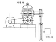
- The coupler shall be firmly connected the input and output shafts. And two shafts shall be paralleled. The base shall be anchored with proper bolts.
- All the components shall be properly assembled to the shaft. Hammering and over-tight assembly which could damage the bearing are not allowed.
- The pulley, chain pulley and gear shall be assembled as close as possible to the gearing so as to reduce curving stress to connect the output shaft shall be properly chosen(within 6 time as large as the diameter of output shaft) and used in accordance with H7 tolerance in order to keep out of and harm noise and harm to the shaft surface.
- Proper amount of grease can be applied to the input bore of the additional motor board to ensure the hole from over-wearing and making abnormal noise.
- The application of anti-rust paint can keep the shaft form rusting.

SELECTION OF LUBRICATION OIL
Proper viscosity of lubricant is contributive to ease the friction of worm gears, so that the speed reducer can fully apply its function in the case of high load or impact load. The table below shows the selection of lubricants for “REGAL” speed reducers:
|
LOAD
|
SHELL OIL
|
MOBIL OIL
|
ISO VG
|
|---|---|---|---|
|
COMMON LOAD
|
OMALA OIL 150
|
MOBIL GEAR 629 |
ISO VG BP 150
|
|
OMALA OIL 220
|
MOBIL GEAR 630 |
ISO VG BP 220
|
|
|
OMALA OIL 320
|
MOBIL GEAR 632 |
ISO VG BP 320
|
|
|
HEAVY LOAD |
OMALA OIL 220
|
MOBIL GEAR 630 |
ISO VG BP 220
|
|
OMALA OIL 320
|
MOBIL GEAR 632 |
ISO VG BP 320
|
|
|
OMALA OIL 460
|
MOBIL GEAR 634 |
ISO VG BP150
|
NOTICE
- REGAL speed reducers use KUOKUNG limiting-pressure engine oil HD-320
- After initial 100-hour running, clean the internal part and replace with new lubricant; then, do it every 2500 hours.
- If used for special conditions at high speed, high temperature, low speed, heavy load, and forced lubrication, please contact us for instructions.
- Insufficient lubricating oil may lead to the rapid wear of worm gear and low efficiency.
- Lubricant insufficiency could cause noise and fast abrasion of gears.
- Execssive lubricant could lead to leakage.
- Please fill proper quantity of lubricant to above half of the oil meter (see oil level gauge)
TEMPERATURE
|
AMBIENT TEMPERATURE
|
THE LIMITED TEMPERATURE OF REDUCER
| |
|---|---|---|
|
HOUSING TEMPERATURE
|
LOCAL TEMPERATURE
| |
|
ABOVE 30°C
|
90°C
|
100°C
|
|
BELOW 30°C
|
90°C
|
90°C
|
- AMBIENT TEMPERATURE:This is the environment temperature where the worm gear reducer is operating. Applicable ambient temperature may vary according to location.
- HOUSING TEMPERATURE:The maximum allowable temperature of the reducer housing while it is running.
- LOCAL TEMPERATURE:The maximum allowable temperature of reducer parts while running – normally indicating the position of bearing located at the worm shaft input end.

